Below is the S-101 section of the Portrayal Control File.
<!-- S-101 using SVG simplified points with symbolized boundaries --> <PresentationOptions Type="XSLT" Name="S-101 Draft Symbolized Boundaries" Description="S-101 Draft Symbolized Boundaries"> <XSLTRules Profile="%S100Config%\system\Portrayal\S-101\s101PortrayalProfile.xml" Rulefile="%S100Config%\system\Portrayal\S-101\Rules\main_SimpleSymbols.xsl"/> <SymbolFiles Directory="%S100Config%\system\Portrayal\S-101\symbols" Type="SVG" /> <LineStyles Directory="%S100Config%\system\Portrayal\S-101\LineStyles" Schema="%S100Config%\system\Portrayal\S100LineStyle.xsd" /> <AreaFills Directory="%S100Config%\system\Portrayal\S-101\AreaFills" Schema="%S100Config%\system\Portrayal\S100AreaFill.xsd" /> <ColourFiles Directory="%S57Config%\symbolization\colcalib" /> </PresentationOptions> |
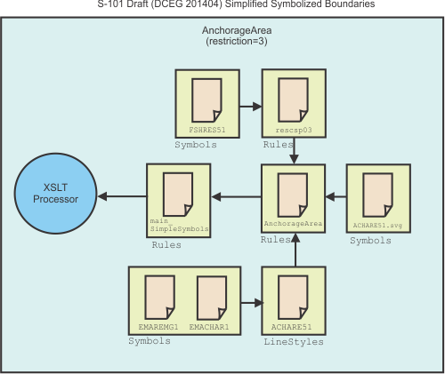
The following image shows how S-101 files (e.g. ACHARE51 FSHRES51) are used to draw an Anchorage Area feature. Symbols and files. The files are shown in their respective folders (Rules, Symbols, and LineStyles).
S-101 uses XSLT (Extensible Markup Language Stylesheet) files that are run through an XSLT processor.
In the Portrayal Control file, the path for S-101 XSLT file, main_SimpleSymbols.xsl is referenced from the <XSLTRules> tag. See below.
<XSLTRules Profile="%S100Config%\system\Portrayal\S-101\s101PortrayalProfile.xml" Rulefile="%S100Config%\system\Portrayal\S-101\Rules\main_SimpleSymbols.xsl"/> |
The main_SimpleSymbols.xsl file lists other XSLT files that are responsible for drawing text and features in S-101 charts.
Because the feature is an Anchorage Area, drawing instructions are read from the AnchorageArea_Symbolized_Boundaries.xsl file. An entry for this file in main_SimpleSymbols.xsl is shown below:
<!--Include templates/rules for: AnchorageArea--> |
<xsl:include href="AnchorageArea_SYMBOLIZED_BOUNDARIES.xsl"/> |
The Anchorage Area is a composite of point and line objects. Point information is read from the <pointInstruction> element in AnchorageArea_Symbolized_Boundaries.xsl. See below.
<pointInstruction> <featureReference> <xsl:value-of select="@id"/> </featureReference> <viewingGroup>26220</viewingGroup> <displayPlane>UNDERRADAR</displayPlane> <drawingPriority>9</drawingPriority> <symbol reference="ACHARE51"> <areaPlacement placementMode="VisibleParts"/> </symbol> </pointInstruction> |
The <symbol reference="ACHARE51"> element refers to the anchorage symbol that is drawn in the centre of the area.

Symbols are stored as Scalable Vector Graphics (SVG) in the symbols folder that is set through <SymbolFiles/> section of the Portrayal Control File.
Information for the border around the anchorage area is contained in the <lineInstruction> element in AnchorageArea_Symbolized_Boundaries.xsl:
<lineInstruction> <featureReference> <xsl:value-of select="@id"/> </featureReference> <viewingGroup>26220</viewingGroup> <displayPlane>UNDERRADAR</displayPlane> <drawingPriority>9</drawingPriority> <lineStyleReference reference="ACHARE51"/> </lineInstruction> |
The <lineStyleReference/> tag sets the line style to the ACHARE51 XML file.
The LineStyles folder that contains the line style XML files is set through the <LineStyles/> tag for S-101 in the Portrayal Control File.
Drawing instructions for Anchorage Area borders are read from the ACHARE51.xml file in the LineStyles folder. See below.
<?xml version="1.0" encoding="ISO-8859-1"?> <?S100lineage source="S52Preslib4.0" format="S100Ed2" version="0.1" creationDate="2015-03-13"?> <?S100Meta name="ACHARE51" exposition="boundary of an anchorage area"?> <lineStyle> <intervalLength>32.3</intervalLength> <pen width="0.32"> <color>CHMGD</color> </pen> <dash> <start>2</start> <length>6</length> </dash> <dash> <start>18.2</start> <length>6</length> </dash> <dash> <start>26.2</start> <length>6</length> </dash> <symbol reference="EMAREMG1"> <position>5</position> </symbol> <symbol reference="EMACHAR1"> <position>13.1</position> </symbol> <symbol reference="EMAREMG1"> <position>21.2</position> </symbol> <symbol reference="EMAREMG1"> <position>29.3</position> </symbol> </lineStyle> |
From the above, border symbolization for the Anchorage Area feature consists of dashes along with two symbols: EMAREMG1 and EMACHAR1. Both symbols are Scalable Vector Graphics (SVG) and are located in the Symbols folder.
The Anchorage Area feature also has the attribute restriction=3 which means that fishing is prohibited. Attribute information is contained in another XSLT file, RESCSP03 that is called from AnchorageArea_Symbolized_Boundaries through the <call‑template> element.
<xsl:call-template name="RESCSP03"> <xsl:with-param name="viewingGroup">26220</xsl:with-param> <xsl:with-param name="displayPlane">UNDERRADAR</xsl:with-param> <xsl:with-param name="drawingPriority">9</xsl:with-param> </xsl:call-template> |
The following instructions are read from RESCSP03:
<xsl:when test="restriction = 3 or restriction = 4 or restriction = 5 or |
restriction = 6 or restriction = 24"> <!-- No Fishing --> <xsl:choose> <xsl:when test="restriction = 13 or restriction = 16 or restriction = 17 or restriction = 23 or restriction = 25 or restriction = 26 or restriction = 27 "> <xsl:text>FSHRES61</xsl:text> </xsl:when> <xsl:when test="restriction = 9 or restriction = 10 or restriction = 11 or restriction = 12 or restriction = 15 or restriction = 18 or restriction = 19 or restriction = 20 or restriction = 21 or restriction = 22"> <xsl:text>FSHRES71</xsl:text> </xsl:when> <xsl:otherwise> <!-- draw centred symbol FSHRES51 --> <xsl:text>FSHRES51</xsl:text> </xsl:otherwise> </xsl:choose> </xsl:when> |
Since the only restriction is 3 (no fishing), the FSHRES51 symbol is used.
All these files combine to draw the Anchorage Area.