The following illustrates how a point is checked for significance.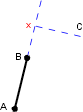
Line patterning commands, combined with optional qualifiers, are grouped to form a line pattern definition. Line pattern definitions are used to display map features in symbolized form when the Symbolize Edges option is active (Tools > Options > Display tab > Symbolize Edges).
Line pattern definitions are stored in the master file. You can associate a line pattern definition with any line feature.
This section describes the line patterning commands and qualifiers and how they are combined to form line pattern definitions. You should be familiar with the master file, as described in “Master File” on page 9.
Some lines are symbolized by adding symbols to one side of the line. The right hand rule is used to determine which side of the line the symbols are to be put. If your right hand is placed on the line with the fingers pointing in the direction of digitizing, the thumb indicates the side on which the symbols will fall.
A point on a point-to-point line is significant if the change in direction of the line at that point exceeds a specified tolerance. This tolerance is determined by the setting of the /TOL qualifier to be explained later in this chapter.
The following illustrates how a point is checked for significance.
Points A, B and C form part of the line to be symbolized. The line segment A-B has just been symbolized and point C is to be tested for significance. If the perpendicular distance from C to the extension of the line segment A-B is greater than or equal to a tolerance (specified using the TOL qualifier), then a new line pattern will begin at point B. Point X in the above diagram represents the intersection of the perpendicular from C and the extended line segment. It is the distance from point X to point C which is checked against the value of TOL to determine whether point C is significant or not.