Menu | File > New > Model |
Tool |
|
The EVRT (Enhanced Vertical Wall) Engine simplifies processing of vertical structures by transforming 3D sonar and lidar data into a horizontal reference system. This is done by using a reference model alignment feature as a CRS and transforming the data from its current CRS to the horizontal CRS of the alignment. The data can then be loaded in the Subset Editor with the 2D Slice visible on the vertical data, allowing simpler analysis of the vertical data.
The transformation is performed using the Chain, Elevation and Offset values of the model alignment as the X, Y and Z values for the data.
• The Chain value of the model is used as the X axis value for the data and will always start with a value of 0 at the beginning of the alignment.
• The Elevation value of the alignment is used as the Y axis value for the data.
• The Offset value of the alignment, which is the distance between the alignment and the vertical wall data, is used as the Z value of the data.
Procedure
1. Open the relevant trackline data and accompanying gridded data.
2. With the trackline layer selected in the Layers window, select the New Model command.
Menu | File > New > Model |
Tool |
|
The New Reference Model dialog box is displayed.
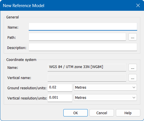
3. Complete the necessary fields and click OK.
The reference model is created and a ReferenceModel layer is added to the Layers window. An alignment can now be added to the model. This is the alignment that will be used as the CRS to transform the data. It is important that the alignment be created along the vertical wall of the data, starting at the end of the data that will use the 0 value as the X axis value. See Alignments for information on the types of alignments and how to create them.
NOTE: Compound alignments can be used, however, a gridded surface will be created from the alignment and converted to the CRS of the alignment during this process. Once that has been done, converting the gridded surface back to the original UTM CRS is currently not supported. |
4. Select the ReferenceModel layer in the Layers window and select the Digitize Alignment command.
Menu | Create > New Model Feature > Alignment > By Digitizing |
Tool |
|
5. Digitize the alignment along the edge of the vertical wall in the gridded data, leaving a small offset between the alignment and the data.
The alignment feature is added to the reference model and is now ready to be applied to the gridded data.
6. In the Model window, expand the Points item and right-click the new alignment feature. If a compound alignment was created, select the parent level for the feature.
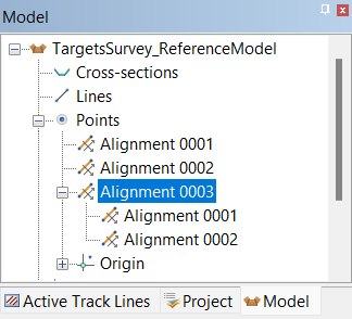
7. Select the Use Coordinate Reference System [Chain, Elevation, Offset] command.
This will cause the data to display in a single line because the data has not been gridded using the CRS of the alignment. A gridded surface should now be created in this CRS to use as a reference surface in Subset Editor.
8. Select the trackline data layer in the Layers window.
9. Select the Tools > Coverages > Grid > Single Resolution Surface command.
The New Regular Gridded Surface dialog box is displayed.
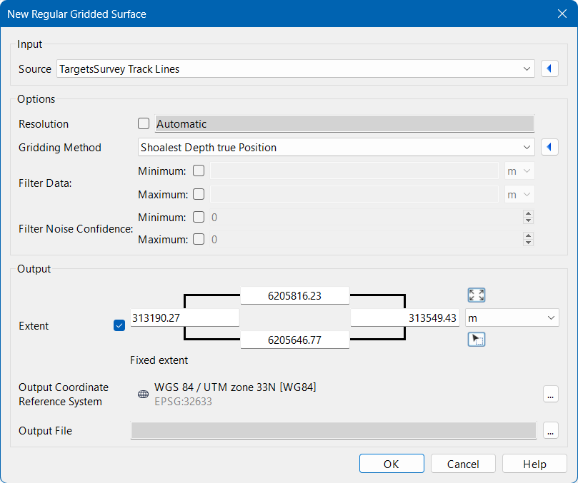
The Filter fields can be used to limit the amount of points included from the seafloor if desired.
10. Click the Browse button (...) for the Output file field and specify a name and location for the output grid.
11. Click OK.
The new surface is created using the CRS of the alignment and added to the Layers window.
12. Open the Subset Editor and load a subset of the data. See Subset Editor for information on the Subset Editor.
Menu | Tools > Editors > Subset > Subset Editor |
Tool |
|
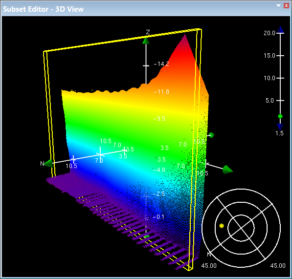
The data is displayed in the Subset Editor - 3D View with the normal horizontal and vertical data, such as a seabed and a quay wall, however right-clicking on the data will display the control axis and the North arrow is pointing up the vertical data.
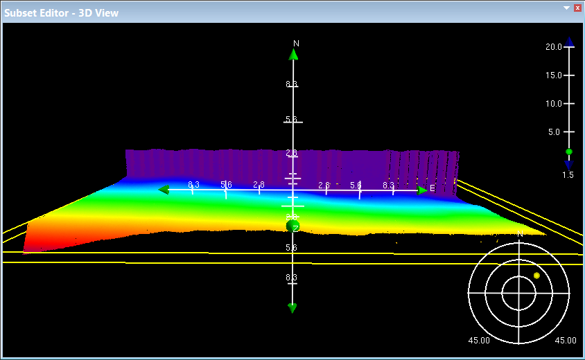
The view of the data can now be flipped to be Z-up, which places the vertical data on the horizontal plain.
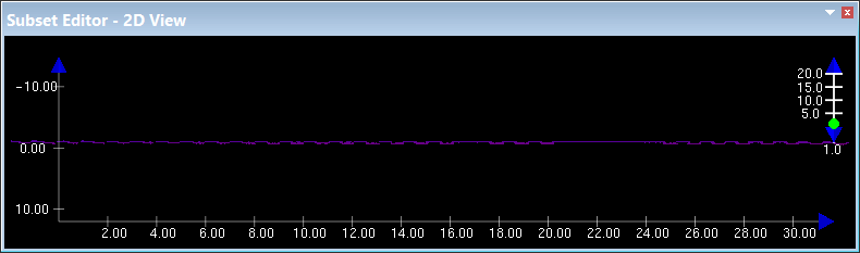
The 2D slice of the subset can now be moved across the vertical data for analysis in the 2D View window and the data edited as needed.
13. Make any necessary changes and close the Subset Editor.
The data can now be converted back to the original UTM CRS.
14. Right-click the trackline data layer in the Layers window and select Use Coordinate Reference System.
The data in the Display window is updated to show the change in the CRS.


