![]() CARIS HPD Source Editor
CARIS HPD Source Editor
Menu | Tools > Limits and Boundaries > Bisector Line |
Tool |
|
This command is only available if the Limits and Boundaries module is enabled. See Modules for further information |
The Bisector Line command creates a line that defines the boundary between two adjacent or opposing areas. This can be used instead of the Median Line command if you want to manually specify the start point for the line.
You must define a source line for both areas and a starting point.
• The source lines can be any lines that represent the coastal boundary of an area, such as baselines.
• The starting point defines the mid-point of the area to be bisected. This can be any digitized point or feature in the area or an end point shared by the two source lines.
The command uses layers to identify the source features, therefore each source line and the starting point must be on a different layer, and at least two of them must be the only feature on the layer. The third feature can be identified by a selection.
If the start point is a shared vertex between the source lines, it will be selected automatically. In this case, only one source line must be placed on its own layer.
You can create layers containing only the required feature using a filtering command. See the section on filtering in the HPD® User Guide.
If one input feature is on a layer containing other features, you must select it before running the command.
Any options defined will be remembered the next time the tool is used.
Related commands:
• • • • | • • • • |
Interface
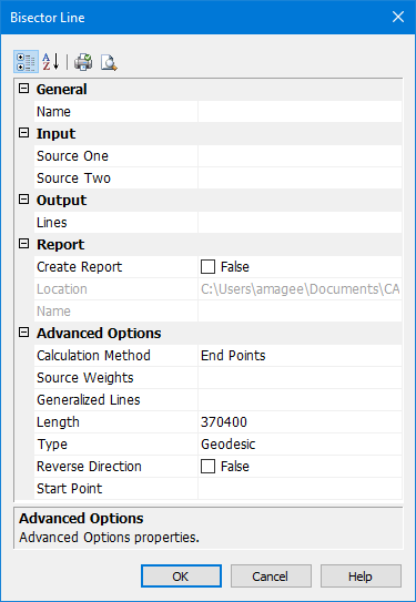
Option | Description |
|---|---|
General | |
Name | The name of the layer on which the bisector line will be created. Select from the list. |
Input | |
Source One | The first source line. If this line is not the only feature on the layer, it must be selected before running the command. Select a layer from the list. If feature is selected, use Superselection or Selection. |
Source Two | The second source line. If this line is not the only feature on the layer, it must be selected before running the command. Select a layer from the list. If feature is selected, use Superselection or Selection. |
Output | |
Lines | The object acronym and attribute values for the bisector line. The list contains the following: • A list of recent objects, if any: Select an entry to reuse a previous object. • Template: Define the feature acronym and attributes using a template. The Select Template dialog box is displayed. • Objects: The Select Object dialog box is displayed. Select an acronym and define the attribute values. |
Report | |
Create Report | True: A report of the coordinates of the contributing points in the source lines is saved as a text file. False: No report is saved. |
Location | The location for the report file. To change the default, click browse (...) and select a new location. This location will be remembered the next time the tool is used. |
Name | The name for the report file. Type a name. |
Advanced Options | |
Calculation Method | For the calculation of the bisector line, only the start and end points in the source lines are used. If the lines have more than two points, generalized lines will be calculated and created on the output layer and will be used to determine the area to be bisected. Choose a method of calculation from the list: • End Points: Generate a straight line for each source line, connecting the start and end point. • Best Fit: Calculate a straight line that best fits all points in the line, beginning at the start point. The generalized lines will not necessarily end at the end points of the source lines. |
Source Weights | If one of the source areas should be allotted more than half of the area being bisected, apply a weight to the areas. Type a two weights separated by a colon in the format For example |
Generalized Lines | The object acronym and attribute values for the generalized lines. The list contains the following: • A list of recent objects, if any: Select an entry to reuse a previous object. • Template: Define the feature acronym and attributes using a template. The Select Template dialog box is displayed. • Objects: The Select Object dialog box is displayed. Select an acronym and define the attribute values. Generalized lines are only created if the source lines each contain more than two points. |
Length | The length of the bisector line, extending from the start point. Because projected and geodetic measurements are not equivalent, the length of the line will be affected by the Type property. |
Type | The type of measurement to use to project the bisector line. Select Loxodrome or Geodesic. This overrides the setting in the Options dialog box, but the Options setting will be used when calculating future measurements of the line. |
Reverse Direction | True: The line is reversed, which means it starts at the widest portion and extends towards the start point. False: The line begins at the start point and extends towards the ends of the source lines where the distance between the lines is the widest. |
Start Point | The start point for the bisector line. If this point is not the only feature on the layer, it must be selected before running the command. Select a layer from the list. If feature is selected, use Superselection or Selection. If the start point is a shared vertex, select nothing. The shared vertex will be selected automatically. |
Toolbar:
Icon | Description |
|---|---|
| Categorized. Display the properties in their categories. |
| Alphabetical. Display the properties in alphabetical order. |
| Quick print. Prints the current settings of the dialog box. Displays a Print dialog box. |
| Print Preview. Displays the current settings of the dialog box. |
Procedure
1. If necessary, select one feature.
2. Select the Bisector Line command.
The Bisector Line dialog box is displayed.
3. Set any necessary options.
4. Click OK.
The bisector line is drawn, along with any generalized lines that are needed. If Create Report is true, a text file containing the coordinates of the contributing points is created.


